📖 About 7 min read
Pneumatic conveying and storage silos are closely interconnected, even when procured as separate packages. Conveying capacity, terminal conditions, silo inlet design, vent-air volume, fines loading, and operating sequence all affect the complete system.
DYPNF Co., Ltd. (formerly Dong Yang P&F) can supply pneumatic conveying systems and storage or blending silos as an integrated package. A common design basis helps EPC contractors and plant owners coordinate these interfaces and clarify performance responsibility.
| Category | Pneumatic Conveying |
|---|---|
| Primary cause | Mismatch of design assumptions at PCS and silo interfaces |
| Key variables | Throughput, material properties, route, operating conditions, terminal and silo inlet conditions |
| Fix level | Integrated PCS and silo engineering based on a common design basis |
| Verification method | Design calculations and representative testing at DYPNF’s pilot test facility — 3 test lines, 3 to 14 inch piping, conveying runs over 150 m |
| Reference base | Plants up to 3,000 KTA at 90 Ton/hr conveying capacity; maximum 132 Ton/hr on a separate 1,000 KTA plant; 9 confirmed PCS and silo integrated scopes (13 including affiliated-company scopes) |
| Related standard | NFPA 660 (effective December 2024) and ATEX, where the project scope requires it |
How does integrated PCS and silo engineering reduce interface risks?
In a polyolefin plant, the PCS transfers powder or pellets from the reactor or extruder section to blending and storage silos. The silos then feed bagging, bulk loading, or downstream processing. If these packages are designed independently, different assumptions may be used for terminal velocity, material temperature, silo inlet conditions, vent-air volume, fines loading, and operating sequence.
Such differences may result in insufficient silo venting, excessive material degradation, unstable operation, or uncertainty over performance responsibility. Integrated engineering allows the conveying conditions, silo inlet, venting, blending operation, and discharge sequence to be reviewed together.
The same interface question appears across DYPNF’s wider reference base, including projects in Indonesia, the UAE, and Vietnam. Across that reference base, plants run different licensor processes — Univation-Unipol, INEOS, LyondellBasell, and Grace among them — and each licensor’s pellet carries its own flow and fines behavior, so the interface has to be designed around the specific material rather than a generic assumption. The reference base also extends beyond polyolefins, including the ABS Project in Saudi Arabia.
The required interface data should be agreed before detailed design is frozen. Typical items include the normal and maximum transfer rates, conveying-air flow and pressure, expected material temperature, allowable silo pressure, filling sequence, control signals, and the responsibility for performance testing. Clear interface data remain necessary even when both packages are placed under one purchase order.
Fines and angel hair require separate consideration. Fines may affect silo vent filters and downstream dust collection. Angel hair is influenced mainly by conveying velocity, pellet temperature, resin characteristics, pipe routing, bend geometry, and internal pipe surface condition. Preventive measures may include a suitable velocity profile, treated pipe surfaces, properly selected bends, and streamer traps.
What determines pipe diameter and blower duty?
Throughput is a key input, but it cannot determine the PCS by itself. The design must also consider material properties, conveying distance and elevation, routing, bends, conveying mode, temperature, pressure, and turndown.
Pipe diameter and air volume are selected together. Excessive velocity can increase pressure loss, energy use, degradation, fines, and wear. Insufficient velocity can cause saltation or blockage. The blower or compressor must provide the required air volume and pressure for the actual route and specified operating cases, including suitable margins.
Across DYPNF’s dilute-phase, dense-phase, and combined-mode references, the range covers plants sized up to 3,000 KTA served at a conveying capacity of 90 Ton/hr — a scale reflected in the Baltic Chemical Complex project in Russia, contracted in 2022 for a 3,000 KTA polyethylene plant — and separately a maximum conveying capacity of 132 Ton/hr on a 1,000 KTA plant. The two figures come from different projects: plant capacity (KTA) and conveying capacity (Ton/hr) describe different things and should not be converted into one another.
| Design input | Principal design effect | Why coordination is required |
|---|---|---|
| Throughput and operating range | Conveying mode, pipe diameter, solids loading | Stable operation is required at design and turndown conditions |
| Material properties | Conveyability, degradation, wear | Materials behave differently under the same air conditions |
| Distance, elevation, routing, and bends | Pressure loss and velocity profile | Actual layout determines blower or compressor duty |
| Material and air temperature | Softening, condensation, equipment limits | Temperature affects product quality and reliability |
| Terminal and silo inlet conditions | Impact, air separation, venting | The conveying line must match the receiving silo |
How does DYPNF support design verification?
Design calculations use project data, established engineering methods, and relevant operating experience. Where material behavior or project conditions require confirmation, representative testing can support the final design. The scope may cover flow behavior, pressure response, degradation, fines, or wear tendency.
DYPNF operates a pilot test facility with three test lines covering piping from 3 to 14 inches, over conveying runs exceeding 150 meters — long enough to represent real plant conveying distances rather than a short bench-scale loop. Flowability, bulk density, particle size distribution, and abrasiveness are measured against the specific material a project will handle, and the results feed into four decisions: conveying distance, operating pressure, air consumption, and system efficiency.
Test results do not replace full-scale engineering. Scale-up must account for the actual throughput, line length, elevation, bend count, destination, and operating sequence. Used correctly, testing reduces uncertainty before fabrication.
Testing is particularly useful for unfamiliar powders, fragile pellets, recycled materials, or products with limited reference data. The test objective and acceptance criteria should be defined in advance so that the results can be translated into specific design decisions rather than treated only as a general demonstration.
What determines silo capacity and configuration?
Silo capacity is based on production and consumption rates, storage time, grade segregation, quality-hold requirements, blending duty, filling and discharge sequences, downstream capacity, plot area, transportation, and site conditions. The filling rate, batch cycle, inlet arrangement, venting, and discharge sequence must still be coordinated with the PCS.
The required inventory should be checked against the usable, rather than gross, silo volume. Freeboard, inlet arrangement, minimum operating level, blending internals, and discharge geometry can reduce usable capacity. Grade-change frequency and the need to keep products separate may determine the number of silos even when the total storage volume is unchanged.
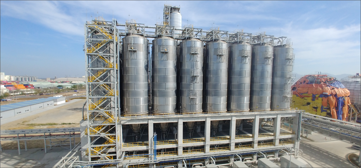
On the SHAHEEN project, a mix of unit sizes was supplied within one scope rather than a single repeated silo design — 30 units at 1,102 m³ and 4 units at 443 m³ — delivered together with the pneumatic conveying package rather than as a standalone silo order.
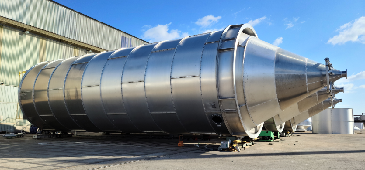
For polymer applications, DYPNF can provide aluminum or stainless steel storage and blending silos. Material and configuration are selected for the product, temperature, environment, structural requirements, and project specifications. DYPNF’s Multi-Tube One-Through concept distributes material through multiple internal paths to achieve homogenization in a single pass without an external recirculation loop.
Where does mechanical conveying fit?
Bulk solids packages may also include belt conveyors, bucket elevators, screw conveyors, or drag-chain conveyors. At each interface, feed rate, transfer-chute geometry, material flow, dust release, control sequence, and maintenance access should be coordinated. DEM analysis may support complex mechanical transfer-chute design, but it does not replace equipment sizing or dust-hazard assessment.
Scale matters here. On a long-distance belt conveyor reference such as the MISR Phosphate project at 3.7 km, upstream simulation is worth the effort because a chute redesign after installation on a multi-kilometer line is a far larger undertaking than a design revision on paper.
Beyond polymer pellets, the mechanical conveying scope covers non-polymer bulk materials including sulfur, coal, and coke, at volumes considerably higher than typical resin conveying, depending on project layout and material properties. Dust and explosion safety on these systems is designed against NFPA 660, effective December 2024, and ATEX where the project scope requires it.
| Scope arrangement | Interface responsibility | Coordination required |
|---|---|---|
| Separate PCS and silo packages | Divided at the battery limit | Terminal conditions, silo inlet, venting, and sequence |
| Separate PCS and MCS packages | Divided at the transfer point | Feed rate, chute or hopper, dust release, and interlocking |
| Integrated PCS, silo, and MCS package | Coordinated in one scope | Common design basis and unified interface review |
Practical value of an integrated package
An integrated scope does not eliminate technical risk or the need for clear battery limits and guarantees. It provides consistent material data and operating cases, clearer responsibility for terminal conditions, fewer conflicting assumptions, and more efficient coordination during engineering and commissioning.
Pneumatic conveying and storage silo packages have been supplied within the same project scope in 9 confirmed cases, extending to 13 when affiliated-company scopes are included. On the SHAHEEN project, 34 aluminum silo units were delivered together with the pneumatic conveying package within a single combined scope.
Frequently Asked Questions
Can DYPNF supply PCS and silos under one contract?
Yes. Integrated or separate supply is possible according to the project scope and agreed battery limits. Both have been delivered within the same project scope in 9 confirmed cases, 13 including affiliated-company scopes.
What plant scale has DYPNF handled?
References span plants up to 3,000 KTA at a conveying capacity of 90 Ton/hr, and separately a maximum conveying capacity of 132 Ton/hr on a 1,000 KTA plant. These are distinct project conditions.
Can the equipment handle non-polymer materials?
Yes. The mechanical conveying scope covers sulfur, coal, and coke, with dust and explosion safety designed against NFPA 660 and ATEX where required.
Does integrated supply guarantee lower fines or angel hair?
No. Any guarantee must be based on agreed material data, operating conditions, test basis, and contractual requirements.
Learn more about DYPNF: